|
Ningbo Zhongce Electronics Co.,Ltd.
|
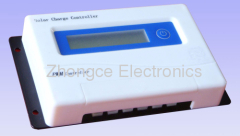
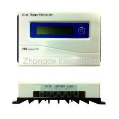
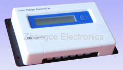
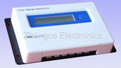
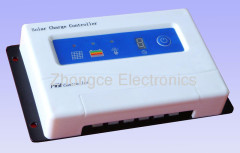
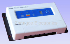
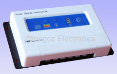
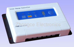
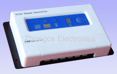
PWM solar charger controller 24V 10A
| Payment Terms: | T/T,L/C,D/A,D/P,WU |
| Place of Origin: | Zhejiang, China (Mainland) |
|
|
|
| Add to My Favorites | |
| HiSupplier Escrow |
Product Detail
CE ,ISO9001 certificate
High efficiency and stability

Solar Charge Controller User Manual
PWM Control Charger
Adjustable Loading Timer
Adjustable Light On + Delay Off Timer
12V and 24V Battery Auto sensing
Preface
Solar Charge Controller is battery charger that can charge batteries by the power from the solar panels. The charge controller is intelligent for charging batteries, using MCU and professional software to control the step of charging, can prolong the batteries' life.
It has full self protection, protection of overload, short circuit, reverse connection, over charging and over discharging etc.
This model controller is 12V/24 Battery Auto-Sensing.
When the Battery is connected to the Charge controller, the controller will detect the voltage of the battery first, then it will decide how to charge the battery connected.
24V20A solar panel charge controller
Specification
Mechanics
Table 2, Delay Time Setting
24V20A solar panel charge controller
Specification
DF-SUN SC30A1224 ( 12V/24V Battery Auto Sensing)
Rated Cable Charging Current | 30A | |
Rated Load Current | 30A | |
System Voltage | 12V | 24V |
Overload, Short Circuit Protection | YES | |
No load current | ≤20 mA | |
Charging Circuit Voltage Drop | Not more than 0.26V | |
Discharging Circuit Voltage Drop | Not more than 0.15V | |
DC Charge Voltage | 14.4V | 28.8V |
Float Charging | 13.7V | 27.4V |
Temperature Compensation | -5mv/℃/2V | |
Automatic Disconnection Output Voltage | 10.5V | 21V |
Control Method | Charge for the PWM pulse width modulation, the control point voltage for different discharge rates of intelligent compensation amendment; | |
Mechanics
Size: 165mm*102mm*40mm
G.W.: 0.4Kg
Environmental conditions
Operating temperature -20°C to 40°C
Storage temperature -20°C to 50°C
Application
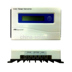
Connecting the solar panel to the solar panel terminals of the charger, "+" to "+" and "-" to “-“.
Connecting the battery to the battery terminals of the charger,““+" to “+" and “-“ to “-“.
Connecting the DC load to the load terminals of the charge, take care of the “+” and “-“ of the DC output.
If the panel is charging the battery, the solar panel LED indicator will be on, and the battery volume LED indicator will display the volume of the battery with different color, from red to green.
Press the power button, will control the DC output ON or Off.
Pressing the power button for about 3 seconds, the figure LED will display “0”, then you release this button, it indicates that the charger enters the timer setup state, at this state, every press of the power button will make the digital change from “0” to “F”, every figure indicates the timer of the load, for example, if you change the digital as “3”, then the charge will switch on the DC output and will auto switch off the DC output in 3 hours. About all figures, see the table 1.
Table 1, DC Output Time Setting
Digital | 0 | 1 | 2 | 3 | 4 | 5 | 6 | 7 |
Timer(hour) | no | 1 | 2 | 3 | 4 | 5 | 6 | 7 |
Digital | 8 | 9 | A | b | C | d | E | F |
Timer(hour) | 8 | 9 | 10 | 11 | 12 | 13 | 14 | 15 |
Pressing the power button for about 6 second, the figure LED will display “0.”, then you release this button, it indicates that the charger enters the delay time setup state, at this state, every press of the power button will make the digital change from “0.” to “F.” to”-.“, every figure indicates the delay time of the load, for example, if you change the digital as “3.”, then the charge will switch on the DC output when the night is coming and it will auto switch off the DC output in 3 hours. When the charger is at the light controlling state, the “.” will be display at the figure LED. If you don't want the light control function, just reset the delay timer to digital “-.”, when the figure is “0.”, the DC output is light controlled, but no delay time. About all figures, see the table 2.
Table 2, Delay Time Setting
Digital | 0. | 1. | 2. | 3. | 4. | 5. | 6. | 7. | 8. |
Delay Timer(hour) | On at night Off at day | 1 | 2 | 3 | 4 | 5 | 6 | 7 | 8 |
Digital | 9. | A. | b. | C. | d. | E. | F. | -. | |
Timer(hour) | 9 | 10 | 11 | 12 | 13 | 14 | 15 | Disable light control function |
Didn't find what you're looking for?
Post Buying Lead or contact
HiSupplier Customer Service Center
for help!
Related Search
Charger Controller
Solar Controller
Solar Charger
Solar Charge Controller
Wind Solar Controller
Solar Remote Controller
More>>


