|
Ningbo Zhongce Electronics Co.,Ltd.
|

Solar System Control Boxes
| Payment Terms: | T/T,L/C,D/A,D/P,WU |
| Place of Origin: | Zhejiang, China (Mainland) |
|
|
|
| Add to My Favorites | |
| HiSupplier Escrow |
Product Detail
1.program timer
2.recognized 12v/24v
3.intelligent controller
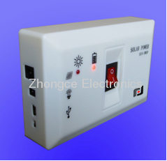
Solar Power Control Box

SUN series solar system control box
Functions
Functions
1), 4-channel DC output. Controlled by 4 switches and a touch button.
2), One channel AC output. Controlled by a switch, AC control box connected to the load through the output sockets.
3), Battery charging function. Using electricity from solar panels to charge batteries intelligently. Application of PWM control mode automatically control the battery charging voltage, and ensure that batteries are not overcharge, thus extending battery life.
4), Battery power display. The use of LED lights on the front panel display battery power.
5), Timing function. DC output with a timing function, from 0.5 hours to 7.5 hours between the timing. So you can control the timing of the DC energy-saving lamps and then shut down from time to time.

Operation Instructions

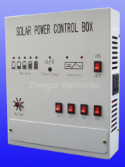
The panel of controller box Introduction
The panel of control box shows as below.
1)Battery voltage/timer display instructions. When in the state of no charge, it shows battery storage of electricity. In the charge state, it indicates the battery charge voltage. The left of the LED lights means charge less, or low voltage of batteries; the right of the LED lights, said higher battery charging voltage or high voltage of batteries. When the battery power falls below a certain value, the first left LED slow blinking, when the battery exhausted, the first left LED flashes quickly, and cut off the DC output. In setting regular time, this 5 LED lights display settings of time, display time from 0.5 hours to 7.5 hours vary, change interval is 0.5 hours. .
2) The load / status indicator. When this LED lights a long light, it said DC main switch open; When this LED lights turned off, it said DC main switch off; When this LED flashes intermittently, it said DC output work in the regular state; When this LED blinking, it said that has entered the regular set state; When this LED flashes fast, it said DC output overload or short circuit.
3) AC output indicator. Lighting expressed an AC output; eliminating means no AC output.
4) AC output fault indicator. When the AC loads due to overload, short circuit, battery voltage is too low, inverter temperature is too high, and then we cut off the inverter AC output, and light this LED lights.
5) AC output switch. Control the AC output on and off.
6) Load switch button / Timing Settings button. This button controls the total DC output switch, and as regularly Settings button
7) DC output switch. 4 switches control 4-channel DC output, respectively
8) Terminal block cover. Open the lid to reveal the external terminals of the control box, all connect to solar panels, batteries, DC output and so on through the terminal block connections.
9) Solar panels charging indicator. When there are solar panels to recharge the battery, this LED lights. Otherwise, this LED off.
Operation Instructions
Load switching operation.
1) AC output switching operation. AC output switch(5) controlled AC output on and off. When the AC switch at the ON position, then the AC output socket of the control box is live.
2) DC switching operation. 4 DC output switches S1, S2, S3, and S4, respectively control the 4-way DC output. The load switch button(6) controls the total DC output.
Timer setting operations(timing is only for DC output valid).
1)Timing Set: Long press the button(6) on the panel about 3 seconds, this time the load /status indicator(2) flashes, that indicates the system entered the state of timing set. In this state, every press at the button(6), the timer adds 0.5 hours, and the battery voltage/timing indicator shows the setting time, maximum time is 7.5 hours. The first left LED on means 0.5 hours, the last right LED on means 5 × 0.5 = 2.5 hours, the rest is analogy. If the set time shows as the right diagram, then the set time can be calculated as follows:(1+2+5)*0.5 = 4 hours. When the timing set has been finished, as long as the button is not operated over about 6 seconds, the state will withdraw from timing set to normal state. At this point the load/ status indicator(2) flashes intermittently, indicating the state of the timing.2) Timing view. In the regular state, if long press the button(6) on the panel about 3 seconds, the system will enter the regular view state, can view the remaining time of the timer. Meantime the system also has entered the timing set state, load / status indicator(2) flashes, if at this time continue to operate button, will change the setting time. Similarly, no action to the button(6) about 6 seconds will out of the state.
3)Regularly launched. If you need to withdraw the state from timing, then the long-press of the button(6) about 6 seconds is needed, this will exit the state of timing.
You can still use the button(6) in the timing state to control the total DC output.


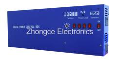
2)DF-SUN C20 Specification
DF-SUN- 300 Configuration:
2)DF-SUN C10 Specification
Working environment
Dimension and weight
Wiring Operation
Open the terminal cover 8, you can see the wiring terminal blocks, upon request, to connect the system. Terminals show as below.
The "+" of "Solar" connects to the positive of solar panels, and "-" connects to the negative of solar panels. "DC" for DC output, "+" indicates the positive of DC, "-" indicates the negative of DC. There are 4 channels of DC output controlled by four DC output control switch, respectively.
Then the battery terminals were red and black, red connects to the battery positive, then the black connects to battery negative.Installation of solar power system
The installation of the solar power system shows as the right diagram.Electrical performance
DF-SUN 600 Configuration:
DF-SUN 600(600W)Inverter,DF-SUN SC20(20A)Charge controller
1)DF-SUN 600 Specification
DF-SUN 600/12-230 | DF-SUN 600/24-230 | DF-SUN 600/12-120 | DF-SUN 600/24-120 | |
Output Continuous Max. Power | 600W | |||
Output Surge Power | 1200W | |||
Converting Max. Efficiency | >88% | >92% | >88% | >92% |
Normal Input Voltage | DC12V | DC24V | DC12V | DC24V |
Input Voltage Range | DC10~15V | DC20~30V | DC10~15V | DC20~30V |
Output Voltage | AC230±5% | AC120±5% | ||
Output Frequency | 50Hz | 60Hz | ||
Output Wave Form | Modified Sine Wave | |||
No Load Current | <0.12A | <0.10A | <0.12A | <0.10A |
Input Low-Voltage Alarm Voltage | 10.5±0.5V | 21±0.5V | 10.5±0.5V | 21±0.5V |
Input Under-voltage Cut off Voltage | 10±0.5V | 20±0.5V | 10±0.5V | 20±0.5V |
Input Over-voltage Cut off Voltage | 15±0.5V | 30±0.5V | 15±0.5V | 30±0.5V |
2)DF-SUN C20 Specification
Rated Charging Current | 20A | |
Rated Load Current | 20A | |
System Voltage | 12V | 24V |
Overload Protection | Yes | |
Short Circuit Protection | Yes | |
Open Circuit Losses | ≤20mA | |
Charging Circuit Voltage Drop | Not more than 0.26V | |
Discharging Circuit Voltage Drop | Not more than 0.15V | |
DC Charge Voltage | 14.4V | 28.8V |
Float Charging | 13.7V | 27.4V |
Temperature Compensation | -5mv/℃/2V | |
Automatic Disconnection Output Voltage | 10.5V | 21V |
Control Method | Charge for the PWM pulse width modulation, the control point voltage for different discharge rates of intelligent compensation amendment; | |
DF-SUN- 300 Configuration:
DF-SUN- 300(300W) Inverter,SUN-C10(10A) Charge controller
1)DF-SUN 300 Specification
DF-SUN 300/12-230 | DF-SUN 300/24-230 | DF-SUN 300/12-120 | DF-SUN 300/24-120 | |
Output Continuous Max. Power | 300W | |||
Output Surge Power | 600W | |||
Converting Max. Efficiency | >85% | >90% | >85% | >90% |
Normal Input Voltage | DC12V | DC24V | DC12V | DC24V |
Input Voltage Range | DC10~15V | DC20~30V | DC10~15V | DC20~30V |
Output Voltage | AC230±5% | AC120±5% | ||
Output Frequency | 50Hz | 60Hz | ||
Output Wave Form | Modified Sine Wave | |||
No Load Current | <0.2A | <0.15A | <0.2A | <0.15A |
Input Low-Voltage Alarm Voltage | 10±0.5V | 20±0.5V | 10±0.5V | 20±0.5V |
Input Over-voltage Cut-off Voltage | 15±0.5V | 30±0.5V | 15±0.5V | 30±0.5V |
2)DF-SUN C10 Specification
Rated Cable Charging Current | 10A | |
Rated Load Current | 10A | |
System Voltage | 12V | 24V |
Overload, Short Circuit Protection | YES | |
Open Circuit Losses | ≤20mA | |
Charging Circuit Voltage Drop | Not more than 0.26V | |
Discharging Circuit Voltage Drop | Not more than 0.15V | |
DC Charge Voltage | 14.4V | 28.8V |
Float Charging | 13.7V | 27.4V |
Temperature Compensation | -5mv/℃/2V | |
Automatic Disconnection Output Voltage | 10.5V | 21V |
Control Method | Charge for the PWM pulse width modulation, the control point voltage for different discharge rates of intelligent compensation amendment; | |
Working environment
Operation temperature: -10℃~40℃.
Storage temperature: -40℃~65℃.
Considerable air humidity should be less than 85%.
No electrical conductivity, dust explosion, corrosion-free gas in the working place.
No shock and vibration in the working place.
Dimension and weight
SUN-SP600 Controller box
Size: 300mm*250mm*70mm
Net weight: 3.5Kg
SUN-SP300 Controller box
Size: 300mm*250mm*70mm
Net weight: 3.0Kg
Didn't find what you're looking for?
Post Buying Lead or contact
HiSupplier Customer Service Center
for help!
Related Search
Control System
Solar System
Access Control System
Automatic Control System
Led Control System
Plc Control System
More>>
Find more related products in following catalogs on Hisupplier.com
Company Info
Ningbo Zhongce Electronics Co.,Ltd. [China (Mainland)]
Business Type:Manufacturer, Trading Company
City: Ningbo
Province/State: Zhejiang
Country/Region: China (Mainland)
You May Like:


Product (124)
- Solar Power System (6)
- Solar Power Box (8)
- Solar Power Inverter (30)
- Solar Charge Controller (12)
- Solar Panels (8)
- Silicon Solar Cell (2)
- Wind Power System (2)
- Wind Power Inverter (4)
- Wind Charge Controller (2)
- Potentiometers (50)
